The Autoflame Flame Safeguard Mini MK8 Controller is an alternative and replacement for the Honeywell RM7800 Flame Safeguard and Fireye E110.

The Autoflame Flame Safeguard has been designed to be an easy replacement for a standard Flame Safeguard. As is the industry standard, the device will monitor the fl ame and control your burner outputs, pre-purge, light off, and release to modulate commands. In addition, you get a reliable, modern design and a customizable interface, along with a wealth of extra safety features.
- Industry-wide compatibility: The included relay module ensures compatibility with all boilers, burners, and control brands in the market.
- Easy setup: Simply interface it with your existing mod motor and thermostat controller.
- Stock available: Reduce downtime and get it delivered from Burner Combustion Systems.
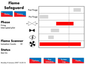
- Customizable touch screen: The 7” touch screen includes a graphical representation of live and historic data, on-screen numerical keypad enabling multi-level password protection, and multi-language support.
- Fully certified: The Autoflame Flame Safeguard is fully certifi ed, UL listed, and FM approved.
- Export and view system reports: The system includes a date & time-stamped fault history, system log, and a system fault output. All reports are downloadable through an Autoflame IR Lead.
- Immediate failure reporting aids quick repairs: Equipped with Direct Modbus and on-board diagnostics.
- Safety options: The system has adjustable safety times, Run Schedule timeclock, Gas Valve Proving System (VPS) and UV, IR, or Flame Rod
flame supervision.
The Autoflame Flame Safeguard unit or MMM8002/FSG is a version of the Micro-Modulating system that provides an easily programmable and flexible means of providing the flame safeguard aspects of controlling a boiler/burner. This control module encompasses all the functions required for reliable flame safeguard management. Built into this system is a fully automated flame safeguard and valve proving system, MODBUS connectivity, and a touchscreen interface. This system monitors the flame safeguard, as it checks on the flame of the burner from the use of a UV, Ionisation, or IR Scanner.
The Flame Safeguard Controller meets the following climate specification:
Climate:
Min. Temperature 0°C (32°F)
Recommended Temperature Less than 40°C (104°F)
Max. Temperature 60°C (140°F)
Humidity 0 to 90% non-condensing
Storage:
Temperature -20 to 85°C (-4 to 185°F)
Protection Rating:
The Autoflame Flame Safeguard Mini MK8 is designed to be panel mounted in any orientation and the front facia is IP65, NEMA4. The back of the unit is IP20, NEMA1
Internal Hardware Status Monitoring
The Flame Safeguard controller analyses the integrity of the internal hardware and diagnostics values for key parameters are available. The relay safety checks are carried out during every startup sequence and their progress will be displayed on the screen.
Inputs Checks
All system input circuits are examined to assure that the Flame Safeguard controller is capable of recognizing the true status of external controls, limits and interlocks. If any input fails this test, a safety shutdown occurs and the fault will be logged.
Cable Specifications
Low Voltage
The screened cable used for low voltage wiring from the Flame Safeguard unit to the detectors must conform to the following specification:
U.V. cable length should not exceed 25m; all other screened cable should not exceed 50m.
- 16/0.2mm PVC insulated overall braid, screened, PVC sheathed.
- Sixteen wires per core.
- Diameter of wires in each core 0.2mm.
- Rated at 440V AC rms at 1600Hz.
- DEF 61-12 current rating per core 2.5A.
- Maximum operating temperature 70oC (158oF).
- Nominal conductor area 0.5sq mm per core.
- Nominal insulation radial thickness on core 0.45mm.
- Nominal conductor diameter per core 0.93mm.
- Nominal core resistance at 20oC. 40.1Ω/1000m.
- Nominal overall diameter per core 1.83mm.
- l factor of braid screen 0.7.
- Equivalent imperial conductor sizes 14/0.0076.
Use the number of cores suitable for the application. A universal part numbering system appears to have been adopted for this type of cable as follows:
• 16-2-2C 2 Core.
• 16-2-3C 3 Core.
• 16-2-4C 4 Core.
• 16-2-6C 6 Core.
• 16-2-8C 8 Core.
(5 Core not readily available)
Note: If using 4 Core cable and interference is detected, use 2 sets of 2 Core.
Data Cable
Data cable must be used for communication connections between MM to BMS systems for Modbus RS485.
Communication cable should not exceed 1km.
Types of data cable that can be used:
- Belden 9501 for 2-core shielded cable (1 twisted pair).
- Belden 9502 for 4-core shielded cable (2 twisted pairs).
- STC OS1P24.
Samples are available upon request. Low voltage and data cable can be ordered from Burner Combustion Systems.
Standards
The Autoflame Flame Safeguard unit has been tested and approved to the following standards:
- UL 372, 5th Edition
- C22.2 No. 199-M89
- S EN 298:2012
- BS EN 12067-2:2004
- BS EN 1643:2014
- BS EN 1854:2010
- ISO 23552-1:2007
- AGA AS 4625-2008
- AGA AS 4630-2005
General Features
No Pre-Purge
It is possible to minimise the burner start-up time by bypassing the pre-purge. The major advantage of this control means that the overall boiler efficiency is increased by minimising the heat loss to the stack during a purge cycle. This means the burner starts-up quicker therefore reaching setpoint in a reduced time. According to the EN676 European regulation, the burner is allowed to restart without a pre-purge if the burner has recycled due to operational temperature/pressure. When the burner is stopped by a lockout then this procedure is not allowed and the burner will have to start-up as normal with a pre-purge. In order for no pre-purge to be active, valve proving must take place and finish successfully. If this valve proving operation is successful then the burner may start-up without a pre-purge.
In order to initiate the no pre-purge feature, option/ parameter 143 must be set to a value of 1. During the first start-up the burner will start with a pre-purge initiated. Once the complete commissioning curve has been entered and the burner has started successfully, the burner will then start-up every time with no pre-purge. If the burner goes above its setpoint and turns off on high temperature/ pressure, then the next time the burner starts-up, it will go through the VPS operation and then light off without a pre-purge, i.e. the burner has shut down in a controlled manner and the gas valves have been checked for integrity.
According to the EN676 regulation, the burner is only allowed to work in this manner if VPS operation has been set to operate before the burner starts up; option/parameter 129 must be set to 0.
The start sequence without pre-purge is as follows:
- Firstly the system goes through its internal tests and relay checks.
- Call for heat on Terminal 57 activates and the system will go through the VPS operation.
- If this operation is successful then the MM will drive the channels to the light off or start position.
- Once all channels reach the start position then the burner will light off.
If the burner shuts down in an abrupt manner, e.g. loss of power to the unit, then the next time the burner starts-up a complete purge will be initiated.
If no pre-purge is enabled in option/parameter 143, and one or more of the following conditions occur, the next time the burner starts up, a complete pre-purge will be initiated:
- • Burner lockout.
- Loss of power to the MM.
- VPS checks have failed.
- MM has been in standby for 24 hours or more.
Note: Pre-purge is only available on fuels which are optioned as gaseous.
Autoflame Flame Safeguard Flame Detection Using Ionisation
As well as using UV or IR, the MMM8002/FSG can detect a flame using an ionisation signal/flame rod. This is wired into terminal 64 and the cable must be shielded.
For ionisation, the flame will be signalled when the rectification voltage is above 30Vdc, the maximum sensed rectification voltage is 540Vdc, above which a Lockout will be generated.
Please check Autoflame Flame Scanners Guide for further details about flame detection options.
Remote Control
Modbus Settings
The data on a Mini Mk8 MM can be accessed remotely either by connecting the MM to a Mk8 DTI, or by using Direct Modbus. Note that only a small subset of this data will be valid when in flame safeguard mode.
There are a limited number of Modbus addresses available on the Mini Mk8 MM which can be accessed directly without the need for a DTI.
When using Direct Modbus, e.g. connecting to Building Management System from the MM without a DTI, then neither Autoflame Intelligent Boiler Sequencing (IBS) nor the DTI can be used.
The MM communicates using an RS485 data link from terminals 27 (-ve) and 28 (+ve). Belden 9501 data cable is recommended.
Up to 10 MMs can be linked together and connected to a Building Management System via terminals 27 and 28. Each Mini Mk8 MM will need to be set with an individual Modbus device ID in option 104.
The maximum block of addresses the Mini Mk8 MM can read and write to is 127, as per Modbus having a built-in limit of 255 byte packets.
If the MM does not receive any Modbus commands for 60 seconds, the Modbus goes ‘offline.’ You can keep the Modbus ‘online’ with a simple instruction, such as polling or setting a single value to that individual MM.
If the MM is powered off or the communications is lost, the Modbus address values from the unit will not be true.
Burner Start-up Sequence
The MM goes through a series of internal checks and flame safeguard checks before starting up the burner; these are relevant to the burner application. Any errors or lockouts which might occur in the start-up sequence will provide information on the time and date they have occurred, and the phase in which it occurred. If any errors or lockouts occur, please contact Autoflame Engineering Ltd or your local Autoflame Technology Centre.
The following start-up sequence is shown for an example burner application. The system has been set up with these burner control features:
- Firing on gas.
- 1 Valve proving system – No vent valve.
- Intermittent pilot.
- UV scanner.
- Air switch on T54.
- Mains Input (T82) – VPS and pressure limits checked.
- VPS operates before start-up.
- Pre-purge and post-purge.
Note that the information above is only a sample of the information available in the AutoFlame Flamesafeguard Mini Mk8 Manual.